Quantcast
Channel: Incredible DIY
Viewing all 31 articles
Browse latest View live

USB to UART Convertors (PL2303 & CP2102)

$
0
0
If you are working with any UART stuff with micro controllers,you may have to debug them or send/receive data with a PC. In good old days,all of the computers got RS232 serial ports and we could use a MAX232 IC to convert RS232 to UART. But in recent years,RS232 ports got vanished in consumer computers specially in laptops (In good old days we got laptops with serial and parallel ports).
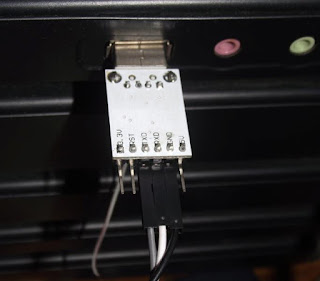
There are many solutions for USB to UART interface but some of them are not really cheap(like FT232). The cheapest way to use a simple USB to UART convertor.I recently got two of them and one is using PL2303HX and other one is using CP2102. Both are compatible with 3.3V LVTTL logic levels as it seems.  If you have an Arduino board you can use them them program the board using the boot loader. The one I got with PL2303HX doesn’t have a pin soldered for automatic reset (it uses the DTR pin on a serial port for resetting) in Arduino programming, but according to datasheet you can solder it to pin 2 on PL2303HX. This a guide with pictures telling you how to do it. CP2102 board got a presoldered pin called RST,but it is for CP2102 reset,So you need to solder DTR pin for pin 28 of CP2102 according to the datasheet.

You can get DTR pre soldered CP2102 from Techkatha. They also get Arduino UNO clone kits for very good price.The service they provide is really good :)

 I got PL2303HX based one for $1.68  and CP2102 based one for $2.13 . I got the both boards with required female to female jumper wires too.
Here I’m testing too boards and you can get drivers from;
PL2303HX Drivers
CP2102 Drivers
DSCF5633
image
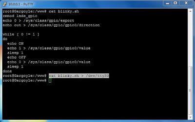
I did a simple echo test using my favourite serial debugging tool SSCOM32 (like good old HyperTerminal) . You can download it from here. The echo test on both modules was a success.
sscom

Modifying a cheap CP2102 USB to UART board to get a DTR pin (for Arduino programming)

$
0
0
I got this CP2102 USB to UART board from ebay recently as showed in my previous post. I got this mostly for Arduino progeamming using the Arduino bootloader in my ATMEGA328. Even though, this board has a pin called RST (Reset), it is not connected to DTR pin of the CP2102 IC. I have seen that many have stated that they had to face a problem in programming an Arduino using CP2102. I also faced this problem first. The problem was we all had tried to use this RST pin as the Arduino reset pin. If you try this you will get following error because this RST pin is actually connected to the Reset pin of the CP2102 itself. So, If you have did this and got this error this guide will help you to correct it and program your Arduino with this board.
Error: “avrdude: stk500_getsync(): not in sync: resp=0x00
When I check the CP2102 datasheet,I found out that the actual DTR pin is at pin #28 of the QFN-28 package.So,the only thing I had to do is soldering a wire to this pin.This is the pinout of the IC according to the datasheet figure:2.
Pinout
Please note that the QFN28 is a really small IC package,You need to have good soldering skills to solder it using a normal soldering iron (like my $1 soldering iron).This is the actual photo of the board,the pin shown by the red arrow is the pin #28 in my case.Compare the pin size with a surface mount resistor.
cp2102
I soldered a jump wire to this pin and used glue to secure the wire as below. The red arrow shows the wire I soldered to the DTR pin.
DSCF5706_640x480
You can test the DTR pin using a terminal program. Here I’m going to use RealTerm for this. Just set the port number on Port tab and toggle the DTR as shown on the picture using DTR Set & Clear buttons. Just measure voltage between DTR & Ground pins when you toggle this.It should be Set=0V and Clear=3.3V if you have done everything correctly.
RealTerm
Now you can use this CP2102 board to program your  Arduino happily. I should thank Kalinga aiya for telling me about this DTR problem on these boards.
This is a really hard work for a beginner. I strongly recommend you to buy a pre-modified CP2102 board for your Arduino if you are going use such a thing for first time. Techkatha shop has this modified board for a very good price and they will ship too. Check there if you need a pre-modified board.

Building an Arduino Pro / Arduino UNO (with TechDuino)

$
0
0
I wanted to build a 3.3V microcontroller development system for a long time. This is because most newer sensors and other  devices are working on LVTTL voltage levels. Now,5V systems are becoming obsolete and even 1.8V systems can be seen. Arduino is an open source microcontroller development system which uses Atmel ATMEGA series microcontrollers. As I found out they can operate at 3.3V at 8Mhz. As AVRs(let’s call them as AVR) are running 1MIPS per 1Mhz,you can get 8MIPS even at 3.3V. Quite impressive isn’t it ?
There is a board called Arduino Pro which is designed to run at 3.3V specially. But the majority uses Arduino UNO which seems to be the most popular Arduino board in present day. When I look for DIY Arduino boards,I found out about the TechDuino which is a custom built Arduino UNO clone with through hole components.
You can buy a prebuilt Techduino or as parts( PCB,uC…etc) separately from the TechShop. They are delivering the items by post and they are nicely packed. The service is awesome in all ways.
As I needed to build an Arduino Pro (as on a Arduino UNO layout,a hybrid of course), I ordered some PCBs for TechDuino and a Arduino Pro(3.3V/8Mhz) bootloader preloaded ATMEGA328 from Techshop. For a PCB & an uC IC is costs Rs700 (US$5.5) and it’s really cheap. Then I had to find a 3.3V voltage regulator and I picked AMS1117-3.3 voltage regulator (You can use any other 3.3 regulator like 7833 or even a LM317 with a proper circuit).I had a bunch of them got from ebay sometime ago.I also got some resisters,capacitors,LEDs,connectors from my stores.
This is the TechDuino PCB I got.
DSCF5714_640x480
Then I soldered the components. You can refer the parts list & buidling notes from here.  I had to do following changes to make it a 3.3V system and suite my other needs.Please compare the changes with the coloured arrows in the picture.
  • Replaced the 7805 with my AMS1117-3.3 (Please note it has different pin out and a surface mount IC,So you have to compare with 7805 pinout and solder using wires or so) [RED]
  • Opted out the DC power jack and soldered a connector to it. [PURPLE]
  • Used a 8Mhz Crystal not a 16Mhz as for the 5V system. [BLUE]
  • Used 100 Ohm resistors in series with LEDs [GREEN]
  • Didn’t have a 4pin push button switch,just used a jumper to make a ground connection as needed [ORANGE]
  • Shorted 3.3V & 5V pins in the board,so that both 3.3V & 5V lines will also have 3.3V
Arduino
After this you can use a CP2102 USB to UART board to connect this to the computer (You may purchase it too at TechShop when you get the PCB…etc).If you have any other please refer my previous post.. Please only connect RX,TX,GND,Reset pins to the programming header. Then connect 5V pin to the external power connector Red wire(shown in purple arrow) if you power the Arduino with USB or else you can power it with external source using the external power connector.
Then download the Arduino IDE from arduino.cc site. Here I’m using Arduino IDE 1.0.3 version. You have to select Tools->Board as Arduino Pro 3.3V/8Mhz.You also have to select the serial port which the Arduino is connected to. The prebootloaded ATMEGA has a pre programed program to blink the LED at Pin13.So,the LED will start to blink when you supply the power.Use an example like led blink on Arduino IDE to test that the everything is working correctly.
ArduinoScrn
Happy Arduinoing!!!! Open-mouthed smile I will show how to build a Arduino powered webserver in my next post Winking smile

Arduino based Webserver (ATMEGA328 + ENC28j60)

$
0
0

As I built a Arduino Pro clone based development board running with 3.3V, I thought to give it a try with my Ethernet module for testing. This is an example for 3.3V LVTTL system. If you use this ENC28J60 on a 5V system,you may have to use logic level convertors.

Ethernet module:

Based on Microchip’s ENC28J60 chip. I’m using a board made by Sure electronics (really good manufacture) called MB-CM14111. I got this 2 years back from ebay for $10. You can now find cheap boards on ebay and do an ebay search as “enc28j60”. ENC28J60 is a SPI device and needed to be connected to ATMEGA328’s SPI module.

Arduino Board:

I’m using my Techduino Pro board which I build on an earlier post along with the my modified CP2102 USB to UART board.

Connections:

I connected the two boards as follows to establish a SPI link between two;

Ethernet ModuleTechduino
3.3V3.3V
GNDGND
DIPin 11
DOPin 12
CLKPin 13
CSPin 10

DSCF5688_640x480

DSCF5693_480x640

DSCF5697_640x480

Software Library:

I used EtherCard Arduino library from JCW’s GIT repository. See here for downloads and installation instructions. You just have to download the zip file and extract it to your Arduino’s library folder(in my case arduino-1.0.3\libraries) and rename it to EtherCard.

Code:

I used a very basic code just to serve a static page from the webserver. You can find many more detailed information on using this library from LUCA’s ENC28J60 tutorials.This is the code I used. You just have to copy this code to Arduino IDE and compile it and upload.Modify myip[] ass you wish.This is the device’s IP address.The library also supports DHCP but here I’m using a static IP for the simplicity.I also omitted the standard HTTP requests/replies on this code for the simplicity.

#include <EtherCard.h>
static byte mymac[] = {0xDD,0xDD,0xDD,0x00,0x00,0x01};
static byte myip[] = {192,168,1,10};
byte Ethernet::buffer[700];
 
void setup () {
  ether.begin(sizeof Ethernet::buffer, mymac,10);
  ether.staticSetup(myip);
}
 
void loop() {
 
  word len = ether.packetReceive();
  word pos = ether.packetLoop(len);
 
  if(pos) {   
    
    BufferFiller bfill = ether.tcpOffset();
    bfill.emit_p(PSTR("<h1>hello</h1>"));
    ether.httpServerReply(bfill.position());
  }
}

Testing:

I connected the Ethernet module to my gigabit Ethernet card using a straight cable (my card auto detects straight or crossover connection).I set my PC’s address to be 192.168.1.1 manually. Then I tried a ping test to the Ethernet module by  “ping 192.168.1.10” on command prompt. It was a success in first round.

Ping

Then I opened my browser and visited http://192.168.1.10 , TaDa!!!! The web page is working Open-mouthed smile

Web

I did a simple packet tracking using WireShark too. Just to see what’s happening there. You can see how  the ping requests and replies going through the network.

Wireshark

Building a SD Card Temperature logger (ATMEGA328 + SDCARD + LM35)

$
0
0
As we built an Arduino powered web server in previous post, let’s build a temperature logger using a SD card this time. I build this because I wanted to see how we can use a SD Card for our projects. The beauty of Arduino libraries are they have a FAT16/FAT32 library. So, we can use a large SD Card without any problem provided that the AVR you use has enough RAM & programming memory. Here I’m using ATMEGA328 which has 2kB RAM and 32kB program memory.

SD Card module:

Here I’m using a SD Card holding module I got a year back from ebay for $1.6. You can even use a microsd card with a microSD to SD card adaptor. Just you have to solder some wires to the adaptor.SD Card pin out is available at pinout.ru site. SD Cards are also using SPI protocol for the communication.

Arduino Board:

I’m using my Techduino Pro board which I build on an earlier post along with the my modified CP2102 USB to UART board. Please note that my Arduino is working at 3.3V.

LM35 Temperature Sensor:

This is a typical analog temperature and you can find the datasheet from here. It has 10mV/Celsius linear scale factor and works at minimum of 4V for full range. According to the datasheet it can be used at less voltages but the measuring temperature range will be very low (check the Minimum Supply Voltage vs. Temperature curve).

Connections:

I connected the two boards as follows to establish a SPI link between two,

SD Card ModuleArduino Pro
3.3V3.3V
GNDGND
MOSIPin 11
MISOPin 12
SCKPin 13
CSPin 10


DSCF5755
DSCF5751

I connected LM35 to the Arduino to get temperature. I connected LM35’s Vout pin to Arduino’s analog input 1 (A0). I also gave power supply by connecting +5V and GND to LM35. I powered up this using the USB power itself and so common ground maintained between Arduino and LM35.

DSCF5752

Code:

I’m here going to use ATMEGA328’s built in 10bit ADC with the Vref=3.3V(Vcc of the uC). You can learn accessing ADC on Arduino by reading this article. The SD card is accessed using the built in SD card library on Arduino. You can learn more about that using this link. As I previously mentioned, LM35 has has 10mV/Celsius linear scale factor. So we have to do a little calculation to obtain the temperature. Here I’m using the full scale ADC method to get the ADC voltage.


So we get total factor as 0.32258 and we have to multiply is by ADC reading to get the temperature value.Here is the final code for the whole thing,

#include <SPI.h>
#include <SD.h>
File myFile;
int x=0;
int tempValue;
void setup()
{
pinMode(10, OUTPUT);
SD.begin(10);
}
void loop()
{
  tempValue=analogRead(A0);
myFile = SD.open("temp.txt", FILE_WRITE);
if (myFile) {
      myFile.print("Temperature ");
      myFile.print(x);
      myFile.print(":");
      myFile.println((long)tempValue*0.32258);
}
    myFile.close();
    x++;
    delay(1000);
  } 

Testing:

I hooked up everything and uploaded the compiled code. The SD card was inserted too. Then I checked the results by reading the SD Card using computer after some time. The results were impressive.

TempLog

Testing a Digital Compass module based on MMC2120MG magnetic sensor

$
0
0

Here I’m going to show you how to use a digital compass for you robot project. This can be easily used to obtain the heading of the robot and adjust the path of it. I got this module and tested it before two years ago. Here,I’m using Sure Electronics DC-SS504 module which includes a MMC2120MG magnetic sensor. Actually this module has the magnetic sensor and a PIC16F690 on-board. This PIC is used here to drive the magnetic sensor and convert it’s I2C interface to UART interface. You can get a digital compass with I2C and drive it using your own uC too. Actually I got this for UART interface and this was used to build a robot.

Unboxing:

The compass arrived with a nice little plastic casing. I had the digital compass module and some 2.54mm connectors.

282657_168290536573363_62333_n

Calibration:

As any other digital compass (including digital compasses on mobile phones), it had to be calibrated for the place where it’s going to use. The typical 8 direction motion was required for the calibration after issuing the calibration command. You can also set the magnetic declination using the appropriate command. You can find those on the datasheet. These calibrations are easy as we use the UART interface provided by on-board uC. I also found out that if we issue the calibration command and don’t move the compass, you can measure the angle reference to that starting point. Cool!!! isn’t it ?

Testing:

I tested the compass by connecting it to the Pickit2 UART tool. Pickit2 got a cool logic analyser feature and UART tool built it. These feature are really helpful when doing projects. You can build your own Pickit2 lite from my previous post.

266821_168305566571860_7908553_o

278297_168305513238532_4680939_o

Video Blog Episode #1 : Unboxing Altera Cyclone IV Development board & module based implementation

$
0
0

In this Incredible DIY video blog episode, I'm unboxing my new FPGA development board which I got from Waveshare Electronics called CoreEP4CE6. It is based on Altera Cyclone IV FPGA (EP4CE6E22C8N) . It is a minimalistic barebone system which only got FPGA, serial configuration device to store code and some LEDs. The all pins are taken out for standard 2.54mm connector header for development. I'm also talking about what are needed for the module based implementation of designs and I'm showing some modules I have.


Connecting Arduino Pro (3.3V/8Mhz) to TV

$
0
0

In this post I’m going to connect my home made  Arduino Pro clone to the television using composite input on the TV. I found a good library called arduino-tvout, but had to modify the hardware a bit to run with 3.3V board as the hardware connections shown in the library site is for 5V systems. Let’ s check the process part by part.

TV connector module:


As the arduino-tvout library wiki has connections for a 5V system,I had to modify it as follows. If you have an idea about composite signals you can understand the modification.

The original connection is like this (Source),

The internal termination impedance of a composite input of a TV is 75Ω. So at 5V,considering only sync resistor, Vid = (75)/(1000+75) * 5V = 0.35V . Actually a standard composite sync level is 0.3V and I used a 680Ω resistor instead of 1kΩ resistor. So, Vid=(75)/(680+75) * 3.3V = 0.33V. Same for the video resistor. As Vid= (75)/(470+75) * 5V = 0.69V, I used a 270Ω resistor to get Vid= (75)/(270+75) * 3.3V = 0.72V. So my TV module’s circuit is as follows and I built this on a veroboard (Cost Rs:25/ $0.2)

image

Arduino Board:


I’m using my Techduino Pro board which I build on an earlier post along with the my modified CP2102 USB to UART board. Please note that my Arduino is working at 3.3V.

Connections:


I connected the two boards as follows, You can get Arduino –> ATMEGA328 pinout from here.

TV ModuleArduino
SyncPin 9 (Pin15/PB1 on chip)
VideoPin 7 (Pin13/PD7 on chip)
GNDGND

DSCF5803_640x480

DSCF5800_640x480

Code:

First of all you have to download the arduino-tvout library from here and extract it into your Arduino IDE’s library folder. I used TVOutBeta1 version for testing. Then I tested this simple code (later I tried a simple counter too). You can get full documentation from the library’s documentation. I tested various resolutions but most of them had synchronization problems(may be due to 8Mhz clock,this library is designed for 16MHz clock systems). I found out that 48*36 resolution in PAL system worked well for me.

#include <TVout.h>
#include <fontALL.h>

TVout TV;

void setup() {
  TV.begin(PAL,48,36);
  TV.clear_screen();
  TV.select_font(font4x6);
  TV.println(0,0,"Hello");
  TV.println(4,12,"incrediblediy.com");
  TV.delay(5000);
}

void loop() {

  }

Testing:

I have tested the circuit on 2 TVs and it worked on the both for 48*36 resolution in PAL system. As I mentioned for other resolutions I got vertical synchronization problems.(May be able to fixing by playing with library headers, I didn’t check yet)

Testing on a CRT TV,

DSCF5791_640x480

Testing on a LED 3DTV,

DSCF5810_640x480


Building Real Time Clock (RTC) module based on DS1307 for Arduino

$
0
0

In this post I’m going to build a Real Time Clock (RTC) module based on popular DS1307 RTC chip for using with Arduino or any other micro-controller platform. DS1307 uses I2C protocol to communicate with the microcontroller.

RTC Module:

This is the circuit we have to build and it has few readily available components. The 3V coil cell battery is used to give backup power to the RTC.  Make sure to solder a 4 pin connector for Vcc,GND,SCL,SDA connections. 1kOhm pull up resistors are used for the I2C bus in the circuit.

DSCF5835_640x480

I got the 32.768kHz Crystal and 3V CR2032 coil cell battery holder from an old computer mother board. I think they are available at any electronic component shop.

DSCF5814_640x480DSCF5823_640x480

After collecting parts I built the circuit on a piece of veroboard. Total cost was around Rs:70 ($0.55). I used 4pin connector for above mentioned connections. If you don’t have a coin cell battery, make sure to short the two battery pins as on the picture,but you won’t have the backup power in case of a power failure.

DSCF5829_640x480

Arduino Board:

I’m using my Techduino Pro board which I build on an earlier post along with the my modified CP2102 USB to UART board. Please note that my Arduino is working at 3.3V.

Connections:

I connected the two boards as follows, You can get Arduino –> ATMEGA328 pinout from here.Even though DS1307 datasheet tells that the operating voltage of the chip is 5V, It worked well even at the 3.3V as I used here. Please be aware of that to avoid unnecessary outcomes.


RTC ModuleArduino
Vcc+3.3V or +5V (As you need)
GNDGND
SDASDA (Analog Pin 4)
SCLSCL (Analog Pin 5)

DSCF5834_640x480

Coding:

You can just write a code using Wire library. Make sure that DS1307 sends 7 BCD digits containing date & time. I was lazy to reinvent the wheel and opted to use the DS1307 RTC library for the Arduino. Get it from here and extract to the libraries folder in your Arduino IDE folder (Rename it to RTC after extracting).I modified the example file to show how to use it.

#include <Wire.h>
#include "RTClib.h"

RTC_DS1307 RTC;

void setup () {
    Serial.begin(57600); // UART initialize
    Wire.begin();
    RTC.begin();
   // RTC.adjust(DateTime("MAY 21 2013","20:40:45")); //you can use this to set initial date/time as you wish
 
}

void loop () {
    DateTime now = RTC.now();
    
// Sending date & time to UART every second    
    Serial.print(now.year(), DEC);
    Serial.print('/');
    Serial.print(now.month(), DEC);
    Serial.print('/');
    Serial.print(now.day(), DEC);
    Serial.print('');
    Serial.print(now.hour(), DEC);
    Serial.print(':');
    Serial.print(now.minute(), DEC);
    Serial.print(':');
    Serial.print(now.second(), DEC);
    Serial.println();
   delay(1000);
}

scrn

Desoldering Surface Mount Devices (SMD)–The hard way

$
0
0

In my previous post, I used some scavenged parts from an old mother board. These old circuit boards are gold mines as they got many reusable components. They may also have very rare vintage chips too. But desoldering SMD is a quite complex task without proper instrument such as hot air gun,reflow oven or a soldering pot. But you can easily desolder SMD components with small pin count. I recommend upto  8 pin or so using this way, If the pins are so close you may try for higher pin count chips too.

You need a normal soldering iron,soldering wire,some tool to push chips and flux would also be helpful in some cases.

My Flux pen (Kester 951):

DSCF5865

My tool(small flat screw driver) to remove chips:

DSCF5867

First you have to apply some flux (if you have) and add some solder to the pins of the chip just as normal soldering.Make two solder blob in both sides like in this picture(only for one side is shown).

DSCF5851

Then simply heat both sides switching between two sides. Don’t take too much time and it will fry your chip. Simply push the chip from the back side using the tool when the solder is melted on pins and chip becomes loose. It will be better to use tweezers to pull up the chip if you have them. I used that flat screw driver as I don’t have a good tweezer. Finally you have to do is cleaning up the board and the desoldered chip. I haven’t used any special thing for it but I think desoldering wick will be helpful.

I have desoldered  this LM431 chip using this technique. You can see the PCB pads where it was soldered in the below picture too.

DSCF5856_792x600

DSCF5863_800x365

Altera Cyclone IV EP4CE6 Testing

$
0
0

As I showed in my previous post,I’m going to test my CoreEP4CE6 board. It is based on Altera Cyclone IV FPGA (EP4CE6E22C8N) . I got my Altera USB Blaster (bought from here) today and tested the FPGA .

I connected the power cable to the FPGA board and connected the JTAG cable from USB Blaster. The both devices were powered by USB. I installed Altera Quartus II Web Edition which is the default IDE for Altera FPGAs. You can download the free web edition from here

I thought to check the board by powering up a LED. I just wanted to connect the LED on PIN11 to Vcc to do this. You can follow the detailed steps on this from here

The schematic diagram:

cct.

The pin assignment (according to the schematic of the board):

pin

The hardware test (you can see the LED in bottom left is ON):

DSCF5880

Programming TI Stellaris LaunchPad on GNU/Linux

$
0
0
TI Stellaris LaunchPad has a quite neat ARM Cortex-M4F based microcontroller and built in ICDI debugging interface. It is a great tool for learning ARM architecture for a small price as $12.99 including FedEX shipping. Now this is upgraded to a better board called TI Tiva C launchpad which has a similar microcontroller. You can see an unboxing video of this launchpad from my friend's site.

Here I'm telling you my experience with this launchpad in GNU/Linux. I'm using Fedora based Fuduntu Linux 2013.1 64bit for this. It is a quite fast and simple linux distribution and it is worth while to try. 

First of all I checked about the device drivers availability for this. I'm using Linux kernel 3.5.8 and it got auto detected without any manual driver installation. Here you can see the output of "lsusb" command.


After some research I found out a great post on Stellaris LaunchPad linux support.
According to that I downloaded the LM4FLASH software source and compiled it. Please note that you need to have LIBUSB-DEV dependency to compile this. You can install it by "yum install libusb*" command. In a debian based distro like ubuntu,you may use apt-get instead of yum package manager. Following commands can be used for the whole process according to that post.

git clone https://github.com/utzig/lm4tools.git
cd lm4tools/lm4flash/
make
sudo cp lm4flash /usr/bin/
 
After that I programmed the "qs-rgb" example from StellarisWare (now TivaWare) to test it.
You can get the TivaWare software library for TI Tiva C series microcontrollers from here.


The flashing was a success and the colour changing of RGB led on the launchpad was working (as for qs-rgb example),

Using TI Stellaris Launchpad as a 10Mhz,8 Channel Logic Analyzer

$
0
0
After Googling a bit about the TI Stellaris Launchpad, I found out that it can be used as a 10Mhz 8 Channel Logic analyzer with some small free softwares. The plugin's home page can be found here and please refer it for the further information about the functions. 

You have to download following for this,


First of all you have to unpack the both files for two folders. Then copy "ols.profile-SLLogicLogger.cfg" file from the plugin to "ols-0.9.6.1\plugins" folder.
Then we have to flash the code into the launch pad. You can flash "sllogiclogger.bin" in the plugin to the launchpad using TI LM Flasher. If you are a linux user, you can refer to my previous post on flashing  Stellaris Launchpad on linux.


Now you can run "ols-0.9.6.1\run.bat" to run the logic analyzer. If you are using Linux, you can run it using "ols-0.9.6.1\run.sh" .

In Logic Sniffer, got to Capture->Begin capture and set the configuration as below. Please note that you have to select COM port (here COM47) according to your Stellaris Virtual port on device manager.


Here I'm testing 3.3V Logic '1' on PB0 pin of the launchpad which is the Channel 0 in the logic analyzer. The results was as on the picture and it was a success. So now you can have your own logic analyzer with TI Stellaris Launchpad.


Introduction to MIPS CPU architecture with AR7240

$
0
0
There are many CPU architectures in current embedded devices. MIPS is also a popular architecture for embedded systems. Here I'm going to play with a MIPS based  AR7240 SoC as my development environment which has a MIPS 24Kc CPU . I'm using a TPLINK-WR740N router as my development board as I don't have any other MIPS development boards. It runs OpenWRT Linux for MIPS (this is not the stock version,I have installed it). So I won't be going to much lower level and I will play at the Linux level like using Linux on Rarspberry PI.

Router specifications:
  • Atheros AR7240@400MHz RAM:32MB Flash:4MB
  • LED * 5
  • Push buttons * 2
AR7240 has following interfaces:
  • LAN * 5
  • WiFi * 1
  • UART
  • USB
  • GPIO (LEDs & Push buttons are already connected)
For testing I just wanted to blink a LED which is connected to the GPIO0 using a shell script.
I found the GPIO mappings from the OpenWRT wiki. The LEDs are already controlled by a module by default and I had to unload it using "rmmod leds_gpio" command. If you are new to Linux, here you can find about Linux kernal modules. I found a great tutorial on controlling GPIOs in any Linux system and I coded a simple shell script to blink the LED connected to GPIO0 in 1 second intervals. Raspberry PI wiki also has a good tutorial on this.

Code:

rmmod leds_gpio
echo 0 > /sys/class/gpio/export
echo out > /sys/class/gpio/gpio0/direction
                             
while [ 0 != 1 ]  
do
  echo "ON"
  echo 1 > /sys/class/gpio/gpio0/value
  sleep 1
  echo "OFF"
  echo 0 > /sys/class/gpio/gpio0/value
  sleep 1
done  

I logged into the router with "ssh 10.0.0.1 -l root" and made a shell script called blinky.sh with above code using echo command (echo "the above code"> blinky.sh). You can create the blinky.sh file on PC and upload it to router using a SFTP client too. Then I made it executable with "chmod +x blinky.sh". Finally I run the script using "./blinky.sh" and it was a success.
(In below photo, the error is because I already unloaded the leds_gpio module)


Relay board for Parellel port/Microcontroller interfacing

$
0
0
Relays are awesome small devices which could be used to control other devices. The plus point of relays is,they can be used to drive a different voltage level device with complete isolation. In here, I'm going to show you how to build a simple relay drive board for your parallel port interfacing or microntroller interfacing. Basically we are using a simple NPN transistor as a switch to drive a relay. The diode is used to protect the transistor from back e.m.f. generated by the relay coil at transient points (relay on/off). You can use 6V or 12V or any other relay as you wish. The transistor used here is 2SD400 (Ic=1A,Pc=0.75W) which costs around Rs.10 ($0.08). You can use any other general purpose NPN transistor as you wish.

The schematic for a channel:


You can build any number of channels as you wish. Here is a 4 channel board build as above.


You can connect this board to parallel port's D0 to D7 (pin 2 to 9) which belongs to the DATA register of the port. A simple program could be coded to turn on/off the relays connected to the parallel port. Even you can connect this board to a microcontroller and do the same. (Image source:Wikipedia)


MSP430 In circuit programming with MSP430 Launchpad using Spy-Bi wire interface

$
0
0
When we use microcontrollers in our circuits we need to program and debug them in circuits after soldering. Hence, In circuit programming is much useful in such cases. Here I'm going to program my MSP430G2211 microcontroller in a circuit. The programmer I'm going to use is the MSP430 Launchpad. You can get all of them from TI including FedEX shipping.I got them for $4.30 couple of years ago and it was a great deal. This MSP430 value line microcontrollers can be programmed using Spy-Bi wire JTAG interface.

Device connections:

You have to connect SBWTCK(TEST) and SBWTDIO(RST') connections between Launchpad and microcontroller. You may also give power to the device from Launchpad too.

Here is the pinout for my MSP430G2211 from its datasheet.


You may connect the device and Launchpad like this.Use some jumper wires and connect them to the given connector headers on the launchpad.


Now you can use Code Composer Studio or any other software to write code and program/debug it to the microcontroller as they are on the Launchpad itself. I coded a simple LED blink application at P1.0 (pin2) and tested on above circuit which was a success.


Using UART & GPIO with AR7240 MIPS board

$
0
0
As I introduced MIPS based router board which has a AR7240 SoC, I further experimented with it to use GPIO and UART in the chip. I'm using my TPLINK WR740N router for these experiments.
I soldered some wires to the board and took the connectors to the exterior of the router so I can play with it easily. You can find the connections to the GPIO and UART pins in this page.


Then I connected my CP2102 USB to UART convertor to the UART port of the AR7240.


Then I logged into the router console using PuTTY and tried to send some data from the UART port of the AR7240 to the PC. In Linux we can use the highlighted command to send a file to the UART port.


 The test was a success and I got the data to the PC using my favorite terminal program SSCOM32.


Simple LM386 based audio amplifier

$
0
0
I built this simple LM386-N1 based audio amplifier (Gain=200 example on datasheet) for my radio project. Here I'm testing it using a small signal generated by multimeter. You can find the schematic and more information in the datasheet. This is a quick test and I'll explain more details in the future of the project.


Native C programs for ARM based Android phones

$
0
0
You can always use Android SDK to program and build Java programs for android phone which are running on Dalvik Virtual Machine. Recently I wanted to build some native C applications for my phone. As Android is based on Linux kernal, it's matter of finding an appropriate cross compiler for the PC. As I found out there are many toolchains for this and I used Linaro ARM tool chain for Windows (WIN32). This is based on GCC and  I downloaded 2013.05 version and installed it using the installer. Please make sure to tick "add to the PATH" when you installing this.

I wrote this small code to test and saved as count.c ,

#include <stdio.h>
int main()
{
int x=0;
for(x=0;x<11;x++){
printf("%i\n",x);
}
}


Then I compiled it using following command in command prompt,

D:\>arm-linux-gnueabihf-gcc count.c -o count -static

The I copied the binary file to mobile using ADB (Android Debug Bridge), you can do it using a file manager too. Make sure to put the compile binary to /system because you can execute binaries only at there in android system.

D:\>adb push count /system
3049 KB/s (463524 bytes in 0.148s)

Then I logged into android shell using ADB, You may use a Terminal Emulator software on the phone itself.

D:\>adb shell

I got root access and changed the file attributes of "count" binary to make it executable (same as on any Linux distribution). (You can either use chmod +x or chmod 777)

~ # su
root@android:/ # cd /system
root@android:/system # chmod 777 count

I executed "count" and tested ,


root@android:/system # ./count
./count
0
1
2
3
4
5
6
7
8
9
10
11|root@android:/system #

I also tested the program on phone using a terminal emulator too,


Compiling kernel modules for an Android phone

$
0
0
I recently got a USB OTG cable for my mobile phone and I wanted to use my PL2303 USB to UART convertor with it. It is great for the embedded system projects I'm working on. You can follow the below procedure to do it yourself.


Phone kernel : Linux 2.6.32.60-Kappa1.6
PC O/S : Ubuntu 13.04 32bit

1) Check for your kernel info using "uname -a" on either terminal emulator or ADB (use "adb shell" and run it).
My result:  Linux version 2.6.32.60-Kappa1.6 (Ka@Kappa) (gcc version 4.7.3 20130102 (prerelease) (Linaro GCC 4.7-2013.01) ) #94 PREEMPT Sun Apr 28 23:46:13 CEST 2013

2) Get the appropriate kernel source for your kernel. I got 2.6.32.60-Kappa1.6 kernel source from a GIT host using, (If you don't have git installed, you can install it by sudo apt-get install git)
git clone https://github.com/KaSt/Kappa.git

3) Download the appropriate cross-compiler toolchain, I'm using Linaro GCC 4.7-2013.01 toolchain.

4) Extract toolchain to somewhere, I extracted it to, /home/buddika/linaro

5) Set path variable to the bin directory of the toolchain using,
export PATH=/home/buddika/linaro/bin/:$PATH

6) Copy the kernel configuration file to the main folder where kernel source it. I executed following command at there,
cp /home/buddika/kernel/Kappa/arch/arm/configs/ka_coconut_defconfig .config

7) Check MakeFile and config files and edit them to match the kernel magic version(in my case 2.6.32.60-Kappa1.6). I had to edit following line on config file,
CONFIG_LOCALVERSION="$(KERNEL_LOCAL_VERSION)-Kappa $(KAREL)" to
CONFIG_LOCALVERSION="$(KERNEL_LOCAL_VERSION)-Kappa1.6"

8) Check the toolchain's binary directory and find the prefix for the compiler, if you see file like arm-linux-gnueabihf-gcc , the prefix is "arm-linux-gnueabihf-". Note this down for steps below.

9) Go to the kernel source directory, Let's clean the old binary files which may be there.
ARCH=arm CROSS_COMPILE=arm-linux-gnueabihf- make clean

10) Let's run menuconfig to configure the kernel options. This will give you a GUI where you can enable features. Select features you need as modules (in my case usbserial...etc) and press M to build them as modules.
ARCH=arm CROSS_COMPILE=arm-linux-gnueabihf- make menuconfig

11) Finally build the selected features as kernel modules. :)
ARCH=arm CROSS_COMPILE=arm-linux-gnueabihf- make modules

Now you can find the compiled kernel modules at "drivers/usb/serial/" folder in the kernel source folder. If you enabled other functions please check the appropriate folder.

I will show you how to use these newly compiled modules on your phone to use USB to UART module in the next post :D
Viewing all 31 articles
Browse latest View live